Non Linear FDM Toolpath
This is the base pattern I designed in Rhino — a series of overlapping curves inspired by organic repetition. It started from a simple idea, but seeing it build up visually was exciting. This became the foundation for the whole piece.
I used Grasshopper to control all the variables for generating the toolpath — here you can see one of the sliders I created to set the Z clearance. This helped define the height between each pass of the print head.
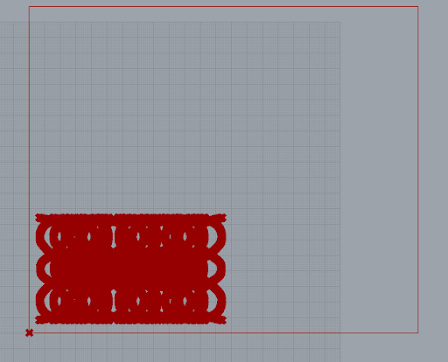
This is the simulated toolpath — basically what the 3D printer will follow. It was interesting to see how clean or messy this could get depending on how the curves overlapped or how I sorted the paths.
I generated the G-code directly in Grasshopper. It includes commands for setting units, homing the printer, and each extrusion point. Writing it this way gave me full control over how the printer interprets my design.
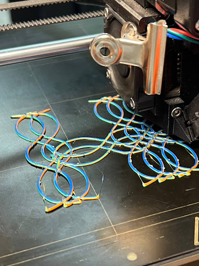
The first layers being printed on the Prusa. This moment always feels satisfying — seeing the digital sketch actually come to life with filament.
You can see the overlapping paths building into a textured, layered form. It was tricky to control the flow when curves got too close to each other.
Here’s the finished piece. Some areas had extra filament threads because of overlapping toolpaths. I learned that using a heat gun helped clean them up. Also, if the path order isn’t right, the piece sags in places — so toolpath logic really matters for a smooth result.
This whole project was about learning to connect design, code, and fabrication. One of the biggest lessons was realizing how much of the final quality depends on small things — curve order, Z clearance, and path overlaps. It reminded me that design isn’t just about visuals, it’s also about understanding how materials behave and how machines respond.


Comments
Post a Comment